We built an X-Y table using the slides that carry the print head and traverses the paper in ink jet printers. The plan was to drive the table using steppers and leadscrews, to serve as a basis for some CNC-type projects.
Platform Experiments:

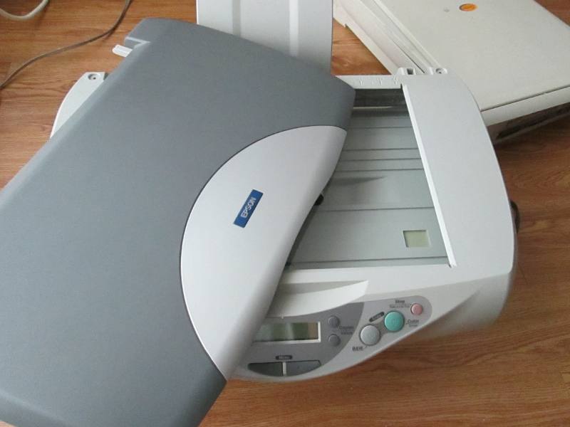
>> Here are some slides that were salvaged from desktop inkjet printers. The black carriages originally held the ink cartridges and some associated electronics. The original design used a toothed belt attached to the carriage, spring tensioned on one end and driven by a stepper with a toothed gear on the other end (seen on the upper right of the picture). This arrangement is designed for moving a light print head with very little force required.
It didn't seem that the 5V motor and the thin belt would hold up if we started moving things heavier than ink cartridges, so we experimented with a lead screw (actually 1/4-20 plated threaded rod) and nut (actually brad hole T-nuts) arrangement. We also replaced the stepper with some 24v units (seen in the bottom of the picture).

<< We did a quick proof of concept to start with. It's important to validate early on in the project that the design choices being made are feasible, so we can minimize bad assumptions that send us back to square one on the design board when we are further into the build. You can design and calculate on paper to get good working parameters, but there's no substitute for physical build tests to be sure, because a theoretical model may not always factor in for variables we might not have accounted for.
The threaded rod worked fine here. We'll probably graduate to using a proper hardened and ground leadscrew with acme threads and a proper leadscrew nut at some time in the future. We're getting some mechanical advantage from the screw, which works to our advantage (we don't need to have high traverse speeds for this project). In addition, the low helix angle of the 1/4-20 screw arrangement is self-locking (axial loads acting on the nut are not able to turn and provide torque on the screw), so the steppers don't really have to provide a holding torque to fight backdriving. This means we can get away with simple step sequences from our stepper driver. We found that it was comfortably able to move a couple of pounds strapped on to the carriage during our load tests.
The 20v laptop power supply hijacked for this project seemed sufficient to feed the motors (we're probably losing a couple of volts dropping through the driver transistors, but the motors and transistors were chugging along fine without overheating for the test loads).
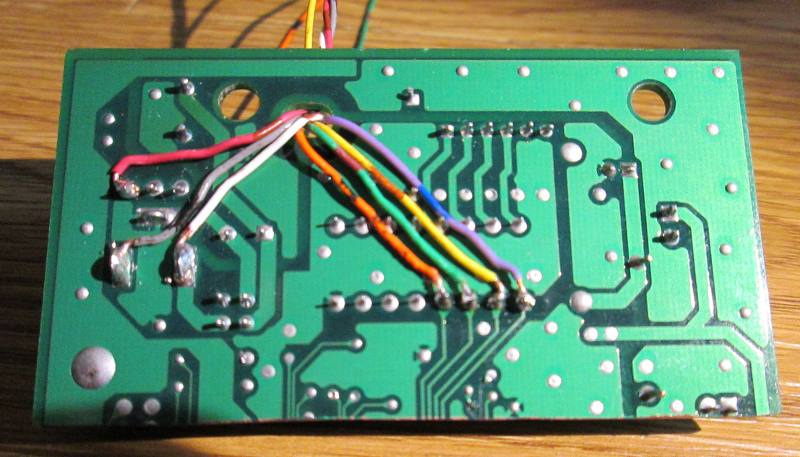
We're also testing out a TIP-120 transistor based stepped driver design (prototyped on the little green board driven by the Arduino).
Leadscrew Nut Design:
Scanner based X-Y Table:
x - axis:
---------
using the scanner stepper and guide. driver is from the original board, by cutting out and
reusing the part of the board that had a ULN2003 and a 7805. The board takes 12v in.
stepper motor
breakout from scanner board:
white: 12v from supply
red: 5v from 7805 output
black/gray: GND

blue
yellow
green
orange

stepping in this sequence moves the carriage from the stepper end to the other end.
about 1024 steps to traverse the length (about 14 inches). the stepper is heavily geared down, so the increased resolution compared to the Y-axis.

y-axis:
--------
using a stepper and guide from an Epson printer. could not reuse the driver from the original board, and this is a bipolar 4-wire stepper, so added a SN754410 chip. Also, the motor shows about 8ohm coil resistance, so this must be a 5v motor, can't use the 12v already available (which would push close to 2amps, and from what i can tell, these motors will do around 1 amp comforatably. used a LM317 to step down from the 12v supply to about 5v (using selected fixed resistors to get the approx voltage).

connected per


on the connector from the stepper, the cable with the stripe on the outside is blue, then yellow, then green the orange is the last connector.


stepping in this sequence moves the carriage from the stepper end to the other end. about 256 steps to traverse the length (about 10 inches). this stepper drives the toothed belt directly, so lower resolution compared to the x-axis.

sample program for testing out the scanner x axis move:
(change loop from 1000 to 250, for testing out the y axis move).


This listing is for the TI Launchpad that was installed to control the steppers.


To check out:
http://www.precisebits.com/tutorials/calibrating_feeds_n_speeds.htm (for CNC routers, good)